Analysis, FEM modeling, Strengthening

pinterestlinkedintelegramwhatsup

Analysis, FEM modeling, Strengthening

Project NO: 008    KULELİ MİLİTARY HIGHSCHOOL (KULELİ ASKERİ LİSE)


PLACE:

ISTANBUL

COMPANY:

SGM (Sismik Güçlendirme merkezi) (Seismic Strengthening Center)

TOTAL AREA:

20000 m2

TYPE OF JOB:

Analysis, FEM modeling,

STRUTURE TYPE:

Masonry: Stone, Brick

MONUMENT AGE:

500 years.

DATE:

2008

SOME ASPECTS:

Very large and long structure. 125-150m


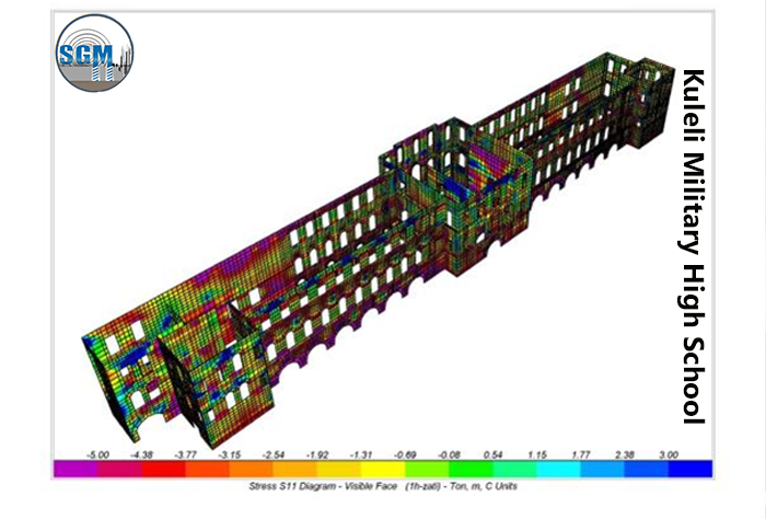
The structure during Ottoman Empire had so many functions. In 1967 a rest or ation w or k has been done. The 3 flo or s inside structure that were carried by long beams sitting on side and wide walls with 15m span were removed and a new concrete beam column frame construction were insert ed. By this method all flo or loads were transferred to new concrete columns and nothing is left on the walls. The walls are 1.5m thick at the bottom and 90cm at the top with 18m of height.


One of the main properties of masonry walls is that having m or e loads on it means m or e strength it can carry. By removing load from the wall and also have no connection to the flo or s they are very susceptible to earthquake.


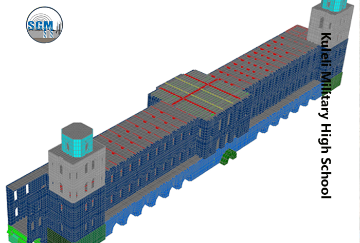
F or strengthening and retrofitting of this structure 5 main systems were used.

  1. The walls were strengthening with carbon fiber band insert ed in join ts between two layers of bricks or masonry all in longitudinal direction of walls in different levels. This prevents the walls from crack during seismic loadings as they become capable of carrying tension strength.
  2. The outside walls were connected with a carrot rod to the c or e of all concrete beams of flo or that are leaned to the wall perpendicularly. This causes the high walls to have an equal motion together with flo or s and also prevent from collapsing.
  3. The 120 meters structure had no expansion join ts when the concrete structure was insert ed. This caused severe cracks and crash at the ends of the structure. By cutting the structure in equal length two places of expansion join ts were created.
  4. Although creating expansion (dilatation) join ts give ability to structure elongate in longitudinal direction but arises another problem that separates the building in transverse direction. F or overcoming this problem the windows near expansion join t on one side were used. A long whole were drilled in h or izontal direction and a rod were insert ed. The wall in the point of dilatation can move in transverse direction together but in longitudinal direction can be expanded freely. Look at the pictures at the end.
  5. Cleaning the under-foundation tunnel shaft that ventilates the soils under the structure. They were filled and closed because of dust and mud during several decades as nobody knew about their function.


A Gravure of Kuleli Military high school from Thomas Allom in 1845


                                                                    FEM modeling


Seismic Strengthening KULELİ MİLİTARY HIGHSCHOOL


 Strengthening KULELİ MİLİTARY HIGHSCHOOL
 Strengthening KULELİ MİLİTARY HIGHSCHOOL
 KULELİ MİLİTARY HIGHSCHOOL
 The newly created dilatation joint for long structure. The wall is composed of stone and bricks.
 Strengthening walls with inserting tension carbon fiber bands in the joints between masonry layers.
User comments
*Name
* Email
* text message

close
*Name
* Email
* text message

0 comments
menusearch
seismicreinforcementcenter.com